AR Glasses Manufacturing: Tooling, Test and ODM Questions for a 0.6-Inch 6000-Nit Display
Building AR glasses at volume is mostly a manufacturing engineering exercise with an optical problem attached. The display is the part the customer judges, so it is also the part where a small process error becomes a visible defect. A 0.6-inch Micro OLED at 1920x1080 with 6000 nits, 120Hz and a MIPI interface gives the product a bright, detailed image, and it defines the fixture, the inspection and the supply conversations that follow. The three areas that decide whether the programme scales are tooling for optical alignment, test coverage that catches what the user will see, and clear agreements with the manufacturing partner.
Key takeaways
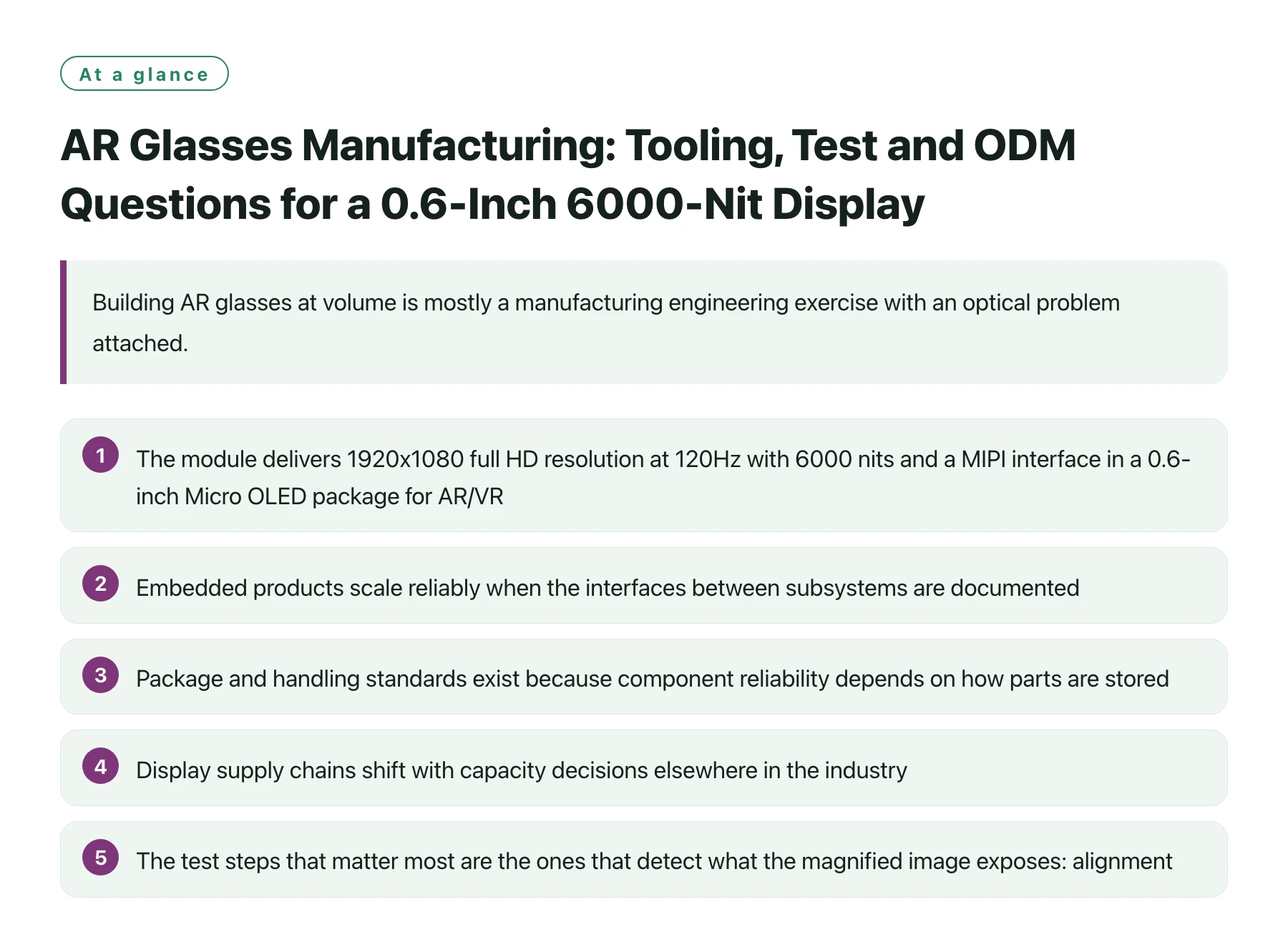
- The module delivers 1920x1080 full HD resolution at 120Hz with 6000 nits and a MIPI interface in a 0.6-inch Micro OLED package for AR/VR, medical imaging and industrial equipment.
- Embedded products scale reliably when the interfaces between subsystems are documented, because units built months apart must behave identically [1].
- Package and handling standards exist because component reliability depends on how parts are stored, transported and processed, not only on how they are designed [2].
- Display supply chains shift with capacity decisions elsewhere in the industry, so a programme needs an agreed change path rather than an assumption of continuity [3].
- The test steps that matter most are the ones that detect what the magnified image exposes: alignment, uniformity, colour and dark-state cleanliness.
AR glasses are assembled from components that are individually well understood and collectively difficult. The optics demand alignment, the electronics demand a quiet electrical environment, and the enclosure has to be light enough to wear and robust enough to survive daily handling.
The 0.6-inch Micro OLED module at 1920x1080 with 6000 nits, 120Hz and a MIPI interface supplies the brightness and detail that a see-through product needs to compete with daylight, while keeping the display small enough to fit beside the optical combiner.
What follows is a manufacturing plan in three parts: the tooling that makes alignment repeatable, the tests that make defects visible before shipping, and the questions that should be answered by a manufacturing partner in writing.
Manufacturing plan for a head-worn display assembly
Tooling and process decisions that determine yield
| Decision | Consequence if handled late | How to settle it |
|---|---|---|
| Optical datum definition | Alignment varies between operators and the defect appears at the customer. | Fix the datum surfaces in the assembly drawing and locate the fixture against them [1]. |
| Harness routing and fixation | Intermittent link faults caused by flex movement in the field. | Specify the route, the radius and the strain relief before cutting the enclosure tooling. |
| Sealing strategy | Ingress or cleaning failures that require a housing redesign. | Decide the sealing method with the environmental requirements, not after the cosmetics are fixed. |
| Brightness operating point | Thermal and lifetime margin committed unintentionally. | Write the default brightness and the thermal test condition into the product specification. |
| Module supply terms | A substitution becomes a redesign under schedule pressure [3]. | Agree notification terms and the parameters that define an equivalent part. |
Design the inspection before the tooling. If a defect can only be found by a skilled engineer looking through the assembled eyepiece, the process has no way to catch it consistently. Decide what the operator will look at, under what lighting, and with what reference sample, then build the station to match.
Questions to put to a manufacturing partner
The first question is who owns the display integration. A partner who assembles the module but does not understand the interface will escalate every link problem to the design team, so the documentation for initialisation, lane configuration and power sequencing should be shared as part of the production package [3].
The second is how appearance defects are judged. Reference samples that show acceptable and rejected dark-state appearance settle more arguments than a written limit, because the judgement is visual and depends on the lighting at the station.
The third is change control. What happens if the module, its flex or its supplier changes? A defined notification path and a re-verification plan protect the programme from a substitution that looks minor on paper and is significant in the assembled product [2].
The fourth is service. A head-worn product will be repaired, and the mechanical design should let the display be replaced without disturbing the alignment of the rest of the optics. That decision is cheapest to make while the housing is still a drawing.
When the module is still being selected, reviewing the 1920x1080 Micro OLED display with MIPI interface mechanical and interface details with the manufacturing partner turns the tooling and test plan into a document based on the real part, rather than a set of assumptions that the first pilot batch will correct.
It is worth adding one practical item to that list: the escalation path. When the pilot line finds a unit that fails the dark-state check or shows an alignment error, someone has to decide quickly whether it is a process problem, a component problem or a design problem. Agreeing in advance who investigates which category, and what evidence they need, keeps a pilot batch from turning into a series of meetings. The answer is usually a short form recording the measured values, the unit serial number and the build station, which is enough to separate a systematic issue from an isolated one.

Sources
Frequently asked questions
What is the critical tolerance in AR glasses assembly?
The position of the display relative to the combiner or eyepiece. Because the image is magnified, small shifts become visible softness or colour fringing, so that relationship has to be defined by datum surfaces and enforced by a fixture.
How should appearance defects be specified for a near-eye product?
With reference samples showing acceptable and rejected appearance, tied to the lighting and viewing conditions of the inspection station. Visual criteria are more reproducible than numeric limits when the defect is judged by eye.
Why does harness design belong in the manufacturing plan?
Because a flex that flexes during assembly or during use will eventually produce intermittent link faults. Bend radius, fixation and strain relief are process decisions, and they are cheaper to make before the enclosure tooling exists.
What change-control terms should an AR programme require?
Notification of any change to the display module, its flex or its source, together with a re-verification path and a definition of which parameters make a substitute equivalent. Those terms prevent a small supplier change from becoming a production problem.